
The new generation of industrial hot gas engines
„We cannot solve our problems with the same thinking we used when we created them.“ (A. Einstein)
 ]
]„We cannot solve our problems with the same thinking we used when we created them.“ (A. Einstein)
From the Stirling engine to the Heat2Power‑Engine – a new generation of externally heated, multi-cylinder, high-performance thermal power engines for industrial waste heat utilization and reliable energy supply, even during periods of low wind and solar output. The technology is based on an advanced system architecture that differs significantly from the classic Stirling principle.
Instead of idealized isothermal state changes, the Heat2Power‑Engine preferentially uses a practical, adiabatic cycle with clearly separated phases for expansion, compression, heat absorption, and heat dissipation. These processes are distributed across specialized components and occur sequentially, but continuously within the overall system.
During expansion and compression, the cylinders remain closed. This eliminates dead spaces between the hot and cold sides. The process operates without internal regeneration because the adiabatic state changes—unlike isothermal state changes—already generate significant pressure and temperature changes, and a regenerator is not required in most applications.
Apparatus concepts for approximating a quasi-isothermal process have nevertheless been developed and are conceptually available. They can be used depending on the application – also in combination with a regenerator – but are not part of the preferred basic adiabatic design.
Due to the temporary complete sealing of the working cylinders, expansion and compression proceed largely adiabatically. This enables high temperature lift and power values, but alters the thermodynamic structure of the process: In the upstream area, instead of a classic isochoric pressure increase, an isobaric pressure increase occurs.
This effect is compensated for by an external thermal module that achieves the isochoric heat absorption and the essential pressure increase outside the cylinders. The thermal coupling is via the cylinder heads, while the specific design of the module remains flexible and application-dependent.
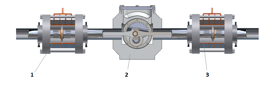
The cylinders are arranged linearly in a boxer configuration and connected by a
Hypocycloid linear guidance![]()
![]() .
For every hot working cylinder, there exists a cold compression cylinder.
.
For every hot working cylinder, there exists a cold compression cylinder.
The adiabatic pressure and temperature changes in the cylinders create a pronounced natural temperature gradient. In many applications, this gradient is sufficient to operate the process efficiently – without internal regeneration.
Depending on the heat source, external modules can be integrated, such as preheating units, high-temperature waste heat exchangers, or thermal storage units. These components may operate outside the working gas circuit and allow for flexible adaptation to different industrial applications.
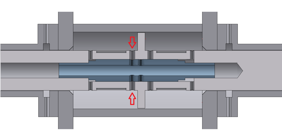
Depending on the design and heat source, the hot and cold gas flows are routed in separate lines and pass through defined functional areas of the system. This results in a stable, uniform gas flow with clear thermal separation between the hot and cold sides.

Heat2Power-Engine - System showing the flow paths
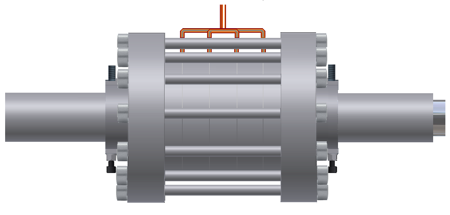
Each double-acting cylinder contains two chambers, one of which is actively connected to the piping system during the stroke – either for expansion or compression, or for emptying or filling.
The corresponding inlet and outlet channels are opened and closed by an extremely simple internal mechanism. This ensures that the flow paths are only opened or closed at defined dead centers – without external valves or complex controls.
The graphic shown represents one possible implementation variant and serves to illustrate the flow guidance.
Show more technical details
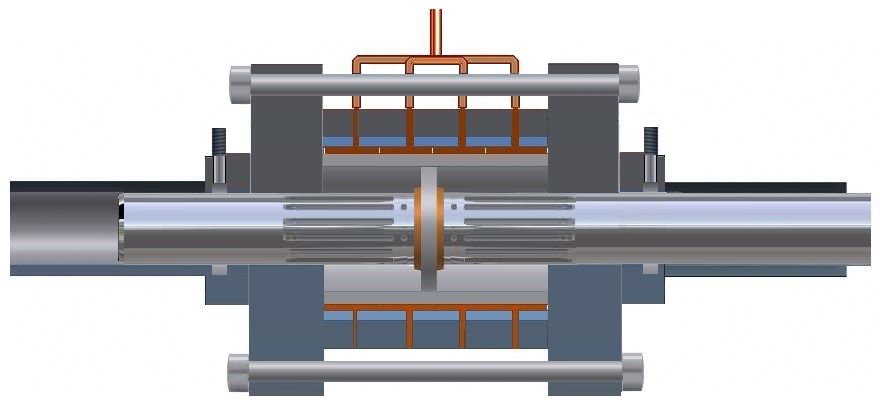
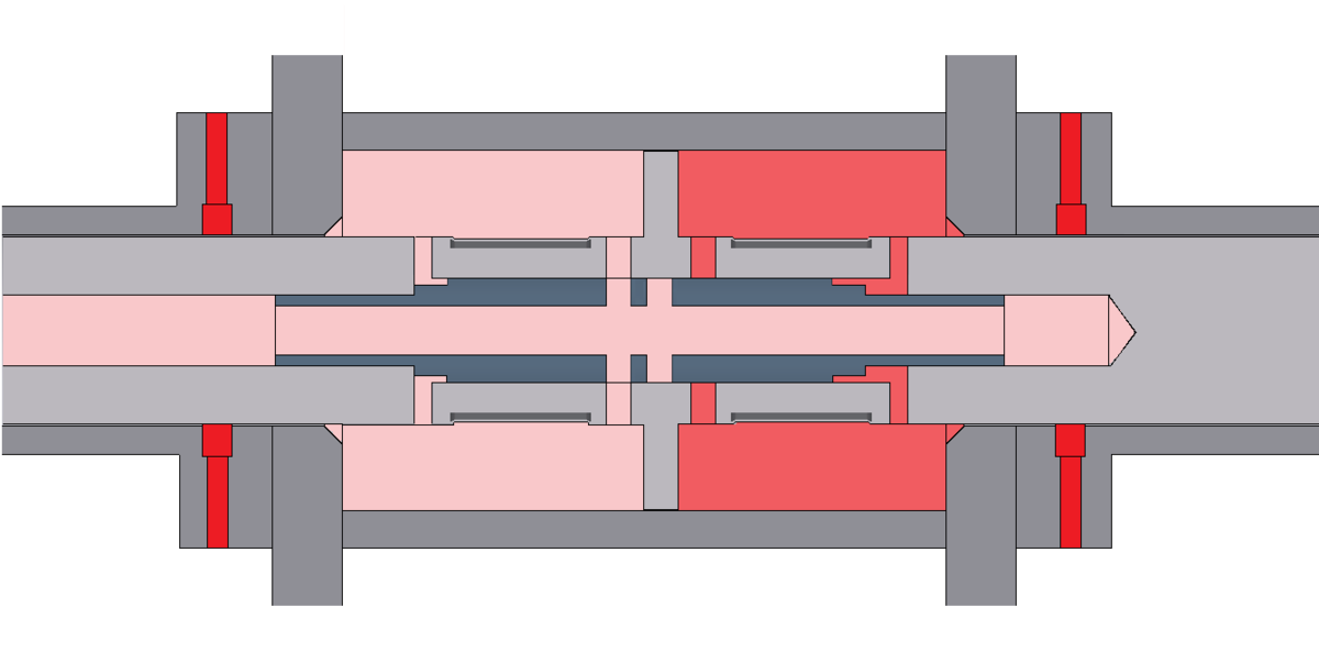
Expansion in the right cylinder chamber pushes the piston to the left.
Expanded gas is expelled from the left chamber.

1 = Expelling gas, 2 = Control piston in left end position, 3 = Expanded gas (here: in left cylinder chamber), 4 = Open exhaust port, 5 = Expanding gas (here: in right cylinder chamber), 6 = Piston rod
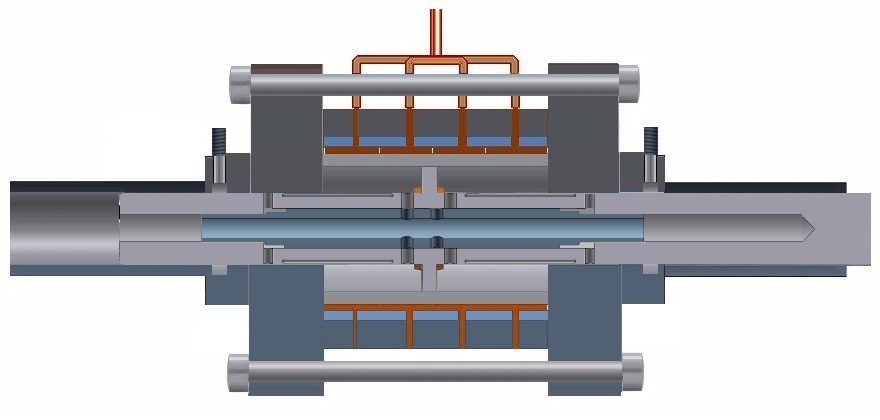
The switching of the flow paths between the cylinder chambers and the piping system is achieved by an internal mechanism that is automatically activated at the dead centers. One chamber opens while the other remains closed – synchronized with the piston movement.
Several design principles are available, including
In principle, this is the implementation of a pulse tube cooler integrated with the compression cylinder.
FAQ - Pressure-controlled switching
[Answer] It must be ensured that no further gas flows in after the expansion process has started.
The switching of flow paths can also be achieved through a purely mechanical solution within the piston rod. In this case, the flow connection between the cylinder chamber and the pipe system is activated at defined dead points by internal moving elements..
The animation shown illustrates one possible variant with mechanically controlled rotary motion. Further versions – including pneumatically or magnetically assisted versions – are conceptually developed.


The Heat2Power-Engine is powered by a central heat source. Depending on the application, various configurations are possible:

The Heat2Power-Engine is predestined for high performance – and delivers it without compromise:
| Losses | internal combustion engine | Heat2Power Engine |
| Friction losses | up to 15 % | up to 5 % |
| Cooling losses | up to 25 % | up to 10 % |
| Exhaust gas losses | up to 35 % | 0 ... 10 % |
| Radiation, wall heat losses | up to 15 % | up to 10 % |
| Combustion losses, charge exchange, purging losses, imperfect thermodynamic process |
up to 40 % | up to 15 % |
| Total: | apr. 65 % (Experience) | apr. 35 … 50 % |
| Residual efficiency (1 – Total) | apr. 35 % (Experience) | apr.. 50 … 65 % |
The Heat2Power Engine systematically reduces all major sources of loss in conventional engines – through low-friction mechanics, the absence of combustion and exhaust gas, complete regeneration, and flow-optimized cycle management. The resulting residual efficiency of 60–65 % is not theoretical, but rather demonstrably achievable and computationally verifiable in conjunction with a suitable temperature range.
How are the favorable values achieved with Heat2Power Technology? Read more about the obvious and undeniable...

